TEVO Tarantula BLTouch Setup
The logical next step to improving your 3D printer experience is an automatically levelled bed. I won’t go into specifics, but the BLTouch is awesome - accurate, simple, and works on any surface. No fuss!
This is a setup guide specifically for the Tevo Tarantula 3D printer. It uses an MKS Base board and runs best with Marlin firmware. Let’s get started!
What you’ll need
- The BLTouch itself
- Servo extension leads (select 60cm male to female)
- A way to mount it
- I use the excellent LPA fan duct - there’s versions for stock and E3D hotends.
- If you have the control board mounted on the printer, I advise mirroring the print so it doesn’t collide with the PCB
- Marlin firmware
- Go to the “Files” section on the Facebook group, scroll down until you find a Marlin zip. I use this version:

- If you are using RC6, this guide supports that too!
- Copy the Configuration.h from ABL_YES into the Marlin folder
Wiring
IMPORTANT IMPORTANT IMPORTANT
Some TEVO Tarantula boards (MKS Base) have SWAPPED POWER AND GROUND PINS. YOU MUST SWAP THE BLTOUCH CONNECTOR OR YOU WILL FRY YOUR BLTOUCH.
The BLTouch connector has 2 connectors:
The main connector is Signal, Power, Ground (orange, red, brown)
Using a pair of tweezers or a toothpick, carefully bend the plastic keeping the Power and Ground pins in place, pull them out, and swap them.
The new order should be Signal, Ground, Power (orange, brown, red)
Note how they match up to the MKS Board:
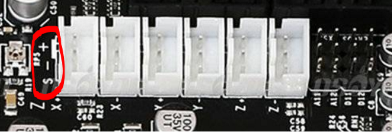
One this is done, attach your 60cm servo extension leads to both cables of the BLTouch. Be sure to line up signal with signal. For the 2 pin plug, just plug it into signal and “power” (which we know is ground).
Plug the 3 wire cable into the bare pins on the right - you want the one marked D11. The signal wire will be right next to the label, and brown (actually power since we swapped) on the back.
Plug the 2 wire cable into the Z- plug. The fit won’t be 100% secure but this is fine. Ensure that if you trace the wires, the pin marked “-” goes to the black wire and the pin marked S goes to the white wire.
Sanity check
Make sure the BLTouch, when retracted, is higher than your hotend. You don’t want it crashing before the hotend does!
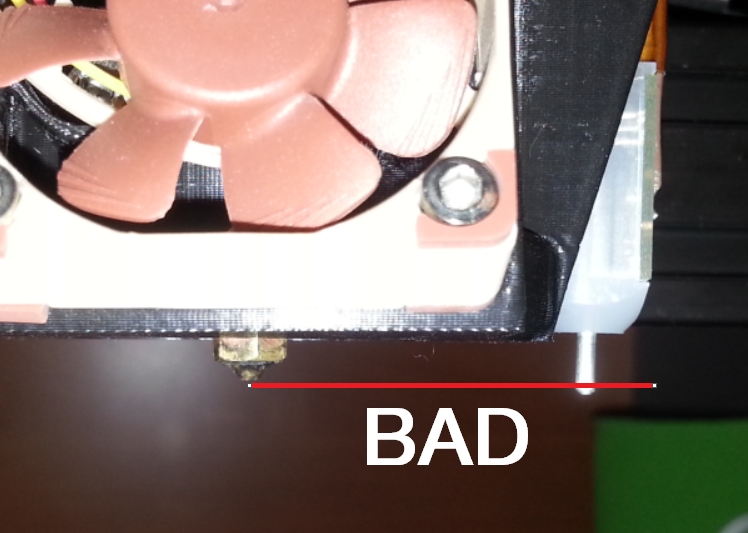
If this is the case, loosen the grub screws holding the heat break into the heatsink. Drop it a mm or 2 and the BLTouch should now clear.
Firmware
Marlin is best. No question. You’ll want to edit Configuration.h to setup the BLTouch.
Find and modify these variables:
const bool Z_MIN_ENDSTOP_INVERTING = false;
Comment out this line by adding “//” to the start:
//#define FIX_MOUNTED_PROBE

#define NUM_SERVOS 1
If you are on RC6:
#define Z_ENDSTOP_SERVO_NR 0
#define SERVO_ENDSTOP_ANGLES {{10,90}}
If you are on RC7:
#define BLTOUCH
You will need to set your probe offsets. Luckily, the LPA fan duct documentation has a handy table for us. Here are mine:
#define X_PROBE_OFFSET_FROM_EXTRUDER 38
#define Y_PROBE_OFFSET_FROM_EXTRUDER -4
Don’t worry about Z offset yet, we’ll get that perfect later.
You may want to slightly increase the Z_RAISE (RC6) settings. I increased them by 1 or 2mm each. If you are on RC7, these are called Z_PROBE_DEPLOY_HEIGHT and Z_PROBE_TRAVEL_HEIGHT.
RC6 only: For some reason, Marlin doesn’t like pulling the probe pin up after the last probe. This is easily fixed:
#define Z_PROBE_END_SCRIPT "M280 P0 S90"
Personally, I don’t like EEPROM, so I disable it. This is entirely up to you.
//#define EEPROM_SETTINGS
If the code won’t compile and warns you about unreachable probe points, you will need to modify them. For example, I had to change LEFT_PROBE_BED_POSITION from 30 to 38.
Calibration
BRING YOUR Z VERY HIGH FOR TESTING
You must give yourself time to abort a test if you set things up incorrectly.
Connect your printer to your computer and start executing some GCode:
G28 X0 Y0; Setup X and Y
G28 Z0
This will begin endstop testing with your BLTouch. Using your hand, manually stop it far above the bed to ensure it works. If it does, then you can proceed:
G29 ; autolevel sequence
Keep a very close eye on the first autolevel - if your offsets are wrong, there is a chance you will run off the bed into air, and crash into the bed.
If this succeeds, great! Now time to calibrate the Z offset.
Using G1 Z{distance} and a piece of paper, move down until you get a decent amount of friction on the paper. Same as manual levelling!
For example, I ran G1 Z0. This far far too high, so I went G1 Z-1. Getting closer, I started going down in increments of 0.1, so G1 Z-1.1 then G1 Z-1.2 etc etc until I found the perfect number.
Once you have this number, enter it as Z_PROBE_OFFSET_FROM_EXTRUDER in the Configuration.h
You’re almost done!
GCode
Finally, you’ll need to modify your GCode to perform an Autolevel sequence (G29) before each print.
Simply find where you have G28 Z0 and put G29 after it.
Comments